Building a Simple Software Defined Network with Ryu and Mininet in Python
SDNs are cool, but there are not a lot of simple and direct guides on how to build one.
So I've decided to cook up a practical guide on how to build an SDN with Mininet and Ryu in python.
This is definitely a

moment
Anywayssss, In this article, I'll show you how to build a simple software defined network, and a controller for this network with Ryu and Mininet, in python (^_^ ).
I'll assume you have basic knowledge of the Linux cli, python, and the SDN architecture
Getting Requirements
First off the OS I'm using for this project is Ubuntu, if you use windows, some commands might not work, so you might have to find an equivalent, or just use WSL.
You would need to install Open vSwitch on your system, if you've not done that before.
Here's a simple guide on how to do that : )
You would also need to install mininet, here's a simple guide on how to install on Ubuntu (You will also find a guide to install it on Windows there).
The python version we would use for this project is 3.9, so let's create a virtual environment with this python version
gift@console:~/Documents/sdn$ python3.9 -m venv sdn-env
Now we can just activate our environment and then install Ryu and Mininet python packages
(sdn-env) gift@console:~/Documents/sdn$ pip install ryu==4.34
(sdn-env) gift@console:~/Documents/sdn$ pip install mininet==2.3.0.dev6
You'll also need to install mininet on your root python path:
$ sudo python3 -m pip install mininet==2.3.0.dev6
We also need to install a particular version of eventlet to prevent some dependency issues
(sdn-env) gift@console:~/Documents/sdn$ pip install eventlet==0.30.2
You don't have to worry too much about what eventlet is, but if you're curious, you can always check online for more info < + >
Network Structure
Before we get to writing the "beans", we first have to talk about how the network would be structured.
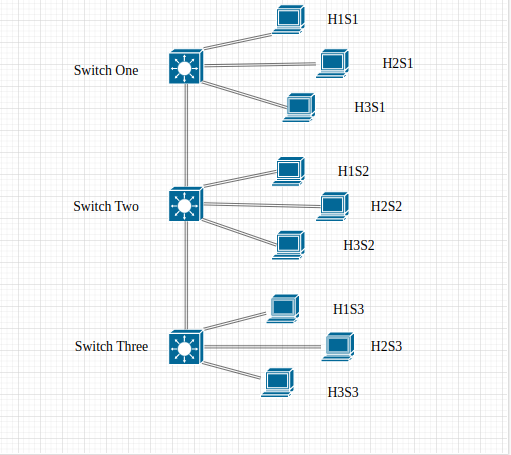
To keep things simple we would build a network with just 3 switches connected serially basically like in a bus topology, and then each of these switches would have 3 hosts connected to them.
The switches we would use are Open vSwitches, which is a really popular option when building SDNs.
The hosts machine this time would basically be a copy of your machine (in my case it would be Ubuntu).
The hosts would have a different network namespace, this means they would have a different network stack from your main system (different IP address, routing tables, interfaces etc). But they would share the same root file system with your computer.
You can actually create network hosts that are isolated from your root file system, by creating them with Docker Images.
We would not discuss this here sha [ -_-]
Here's a visualisation of the network topology:
Network Implementation
Let's get started with building the network, with the mininet python library. Create a file called topology.py
First we would import the necessary modules we need:
from mininet.topo import Topo
from mininet.net import Mininet
from mininet.log import setLogLevel
from mininet.cli import CLI
from mininet.node import OVSKernelSwitch, RemoteController
Next we would create a class that would build the network topology for us. This class would inherit the Topo class we've imported above.
class TopoBuilder(Topo):
	def build(self):
		#create Open vSwitches
		s1 = self.addSwitch('s1', cls=OVSKernelSwitch)
		s2 = self.addSwitch('s2', cls=OVSKernelSwitch)
		s3 = self.addSwitch('s3', cls=OVSKernelSwitch)

		#create hosts
		h1s1 = self.addHost('h1s1', ip='192.168.1.1/8', xterm='xterm h1s1')
		h2s1 = self.addHost('h2s1', ip='192.168.1.2/8', xterm='xterm h2s1')
		h3s1 = self.addHost('h3s1', ip='192.168.1.3/8', xterm='xterm h3s1')

		h1s2 = self.addHost('h1s2', ip='192.168.1.4/8', xterm='xterm h1s2')
		h2s2 = self.addHost('h2s2', ip='192.168.1.5/8', xterm='xterm h2s2')
		h3s2 = self.addHost('h3s2', ip='192.168.1.6/8', xterm='xterm h3s2')

		h1s3 = self.addHost('h1s3', ip='192.168.1.7/8', xterm='xterm h1s3')
		h2s3 = self.addHost('h2s3', ip='192.168.1.8/8', xterm='xterm h2s3')
		h3s3 = self.addHost('h3s3', ip='192.168.1.9/8', xterm='xterm h3s3')

		#Link the network devices to match topology :)
		self.addLink(h1s1, s1)
		self.addLink(h2s1, s1)
		self.addLink(h3s1, s1)

		self.addLink(h1s2, s2)
		self.addLink(h2s2, s2)
		self.addLink(h3s2, s2)

		self.addLink(h1s3, s3)
		self.addLink(h2s3, s3)
		self.addLink(h3s3, s3)

		self.addLink(s1, s2)
		self.addLink(s2, s3)
I believe this is pretty simple to understand (^_^ ).
The Topo class has a build method which we've overridden to defined our topology, with the necessary devices and links.
Now all that's left would be to define our main entry point
if __name__ == '__main__':
	setLogLevel('info') # Add Logger
	topo = TopoBuilder() # Create Topobuilder Object
	c0 = RemoteController('c0', port=6653)  # Connect to our remote controller
	net = Mininet(topo=topo, controller=c0) # Create mininet object
	net.start() # Start the mininet.
	CLI(net) # Run the mininet CLI.
	net.stop() # Close mininet on exit.
This is nice, If you noticed, you'll see that when creating our RemoteController object: c0, I set the port to be 6653, this is where I plan to run our remote controller when We're done building it.
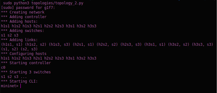
To test the script and see if it's working, run this command:
sudo python3 topology.py
The output should look something like this:
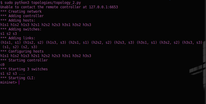
If you notice the second line of the picture says "Unable to contact the remote controller at 120.0.0.1:6653", which is where our SDN controller is supposed to run on.
Let's go on and build the Controller ( ^_^)
The Controller Structure
To quickly recap, an SDN controller is the application in the SDN architecture that manages the flow of data on the network. To put simply, it tells the switches where to send data packets to. This improves the network's performance and allows for more efficient network management.
To build our controller we would use Ryu, which is an SDN framework built with python for building network applications (like a controller -- in our case).
Let's get started by first creating a file called custom_controller.py, and then importing the necessary modules.
from ryu.base import app_manager
from ryu.controller import ofp_event
from ryu.controller.handler import CONFIG_DISPATCHER, MAIN_DISPATCHER
from ryu.controller.handler import set_ev_cls
from ryu.ofproto import ofproto_v1_3

from ryu.lib.packet import ethernet
from ryu.lib.packet import packet
from ryu.lib.packet import arp
from ryu.lib.packet import ipv4
from ryu.lib.packet import icmp
from ryu.lib.packet import ether_types

from ryu.topology import event

import logging
import networkx as nx
Remember to install networkx with pip install you'll see why later
The next step would be to create our controller class, and the __init__ method
class MyController(app_manager.RyuApp):
	OFP_VERSIONS = [ofproto_v1_3.OFP_VERSION]

	def __init__(self, *args, **kwargs):
		super(MyController, self).__init__(*args, **kwargs)

		self.switches = list()
		self.links = list()
		self.hosts = list()
		self.mac_to_port = dict()

		self.net = nx.DiGraph()
The Controller class inherits the RyuApp class, which is the base app for Ryu application.
I also specified the OpenFlow protocol version we would use, version 1.3.
In the __init__ method, I've created some attributes:
- The
self.switchesattribute would store the switch objects for all the switches on the network (3 in our case) - The
self.linksattribute would store the link objects, that defines how the network devices are inter-connected. - The
self.hostsattribute would store the host objects, representing each host on the network (9 in our case) - The
self.mac_to_portattribute is an important attribute that stores the data on the port each device connected to a switch is on. The structure of themac_to_portdict is like this:
{ switch_dpid : {mac_address_of_device : port_device_is_connected_on } }
in the Ryu controller, switches can be referenced (or represented) with their mac addresses. or a given data path ID (dpid). Which is typically just an integer number.
- The final attribute,
self.netis used to create a graph representation of the network, it'll help us to visualize the network, and also in routing data across the network (^_^ )
Now we would have to create methods that would detect when the network devices, their links, and then append them to their respective attributes.
class MyController(app_manager.RyuApp):
	...

	@set_ev_cls(event.EventSwitchEnter)
	def _get_switches(self, ev):
		print(f'New Switch Added: {ev.switch}')
		self.switches.append(ev.switch)
		self.mac_to_port.setdefault(ev.switch.dp.id, {})

		#add switch to netx object
		self.net.add_node(ev.switch.dp.id)

	@set_ev_cls(event.EventLinkAdd)
	def _get_links(self, ev):
		print(f'New Link Added: {ev.link}')
		self.links.append(ev.link)
		self.mac_to_port[ev.link.src.dpid][ev.link.dst.hw_addr] = ev.link.src.port_no

		#link switches in netx object
		self.net.add_edge(u_of_edge=ev.link.src.dpid, v_of_edge=ev.link.dst.dpid)

	@set_ev_cls(event.EventHostAdd)
	def _get_hosts(self, ev):
		print(f'New Host Detected: {ev.host}')
		self.hosts.append(ev.host.mac)
		self.mac_to_port[ev.host.port.dpid][ev.host.mac] = ev.host.port.port_no

		#add host to netx object
		self.net.add_node(ev.host.mac)

		#bi-directional linking
		self.net.add_edge(u_of_edge=ev.host.mac, v_of_edge=ev.host.port.dpid)
		self.net.add_edge(v_of_edge=ev.host.mac, u_of_edge=ev.host.port.dpid)
Now we have created three methods that would be in charge of switches, links and hosts discovery respectively.
The set_ev_class decorator is what enable us to create methods that can handle different kinds of events that can occur on the network.
To detect the events that are related to network device discovery, we use the event module which is from the ryu.topology module.
- To detect the switches, we use the
event.EventSwitchEnterclass. - In the
_get_switchesfunction:- we simply added the detected switches to the
self.switchesattribute, - created a mac-to-port entry for the switches in the
self.mac_to_portattribute, and then, - added the switches to our
self.netattribute as a node (on the graph).
- we simply added the detected switches to the
- To detect the links between different network devices, we use the
event.EventLinkAddclass. - In the
_get_linksfunction:- We added the detected links to the
self.linksattribute, - map the mac address of the destination device to the port on which it's connected for the switch it's connected to (PS. the destination device can be a host, or another switch on the network).
- then we added the link to the
self.netattribute as an edge (on the graph).
- We added the detected links to the
- To detect the hosts on the network, we used the
event.EventHostAddclass. - In the
_get_hostfunction:- We added the detected hosts to the
self.hostsattribute, - we mapped the mac address of the host to the port number on which it is connected to the switch.
- We added the host to the
self.netattribute as a node, - and then we linked the host to the switch bidirectionally on the
self.netattribute.
- We added the detected hosts to the
Now that we've taken care of devices and links discovery on the network, we have to create functions to handle the switch features on discovery which involves setting up basic (custom) configurations for our switches when they are discovered.
To put simply, when a switch is connected to the network, it sends it's features to the SDN controller, when this happens we would typically need to configure the switch to act in a certain way.
In our case, we would configure a default flow rule on the switch.
- A flow rule is a command that tells the switch how to handle a certain kind of packet when it comes into the switch
- Packets can be handled in different ways like;
- forwarding to a certain device,
- dropping the packet or,
- sending the packet to the controller
- Flow rules are added to a flow table, this means that a single switch, can have multiple flow rule, enabling them to dynamically handle different kinds of data packets.
class MyController(app_manager.RyuApp):
	...

	@set_ev_cls(ofp_event.EventOFPSwitchFeatures, CONFIG_DISPATCHER)
	def switch_features_handler(self, ev):
		datapath = ev.msg.datapath
		ofproto = datapath.ofproto
		parser = datapath.ofproto_parser

		match = parser.OFPMatch()
		actions = [parser.OFPActionOutput(
								   port=ofproto.OFPP_CONTROLLER,
								   max_len=ofproto.OFPCML_NO_BUFFER)]
		self.add_flow(datapath, 0, match, actions)

	def add_flow(self, datapath, priority, match, actions):
		ofproto = datapath.ofproto
		parser = datapath.ofproto_parser

		instructions = [parser.OFPInstructionActions(
									ofproto.OFPIT_APPLY_ACTIONS,
									actions = actions)
						]
		flow_mod = parser.OFPFlowMod(datapath=datapath,
									 priority=priority,
									 match=match,
									 instructions=instructions)
		datapath.send_msg(flow_mod)
I'll quickly explain what's happening here now (¬o_o)
- First the
set_ev_classdecorator has been called to respond when a switch sends it's features to the controller using theofp_event.EventOFPSwitchFeatures. TheCONFIG_DISPTCHERis used to indicate that this function should run during the configuration of the switch. - In the
switch_features_handlermethod;- we collected the datapath object which (for simplicity purposes) represents the switch sending in it's features,
- we also collected the open flow protocol object (
ofproto) that the switch uses, and the parser for theofprotoobject (parser) - We then created a
matchobject with no matching criteria, which basically means "match all packets", this will make it possible for all packets to be affected by the flow rule created with this match - The
actionsvariable will instruct the switch to forward all packets to the controller. This is why we have theportparameter of theparser.OFPActionOutputobject set toofproto.OFPP_CONTROLLER, meaning forward the packet to the port where the controller is connected to. Themax_lenvalue,ofproto.OFPCML_NO_BUFFERis meant to ensure that the packet is not truncated, so that the controller can receive the complete packet. - After this we add the flow rule to the switch's flow table with the
self.add_flowmethod
ofproto and ofproto_parser objects are
- The
ofprotoobject is basically a collection of OpenFlow protocol constants. These constants can vary in different OpenFlow versions, so we have to get the OpenFlow protocol version the switch supports. - The
ofprotoconstants could be port numbers, action types, instruction types, flow mod types etc... These are important for constructing and interpreting OpenFlow messages. - The
ofproto_parserobject, is a collection of functions and classes, that helps us parse and generate OpenFlow messages based on the OpenFlow protocol version. - The
ofproto_parserhelps us create OpenFlow messages likeOFPFlowMod,OFPPacketOut,OFPMatchetc. It also helps us to parse messages we receive from the switch into their respective Python objects.
- The
add_flowmethod consists of thedatapath,priority,match, andactionsarguments. I believe you're already familiar with thedatapath,matchandactionsargument ( ^_^)- The
priorityis for setting the priority of a flow rule, this is useful when a packet matches with multiple rule on a flow table. The higher the number, the higher the priority the rule, this means if a packet matches with 2 different flow rules (for example), the packet would be handled based on the flow rule with the higher priority value. - In the
add_flowmethod, we created aninstructionsvariable, this would apply the actions when a packet matches the flow. - The
flow_modobject, to put simply is the flow rule that would be sent to the switch, to modify its flow table - Then
datapath.send_msg(flow_mod)sends the flow modification message to the switch.
- The
Now that we're done with handling switch features, and configuration, we would need to create methods for handling network packets, that are sent to the controller. This would be the last feature we would build for this simple controller.
To keep things as simple as possible, we would focus on handling two packet types, ARP (Address Resolution Protocol) packets, and ICMP (Internet Control Message Protocol) packets.
ARP packets would help us resolve the IP addresses of the network devices to their MAC addresses. This way the switches would be able to update their ARP table (re-actively).
The ICMP packets are what we would use to test if the network can actually send data to different devices on the network. We would do this using commands like ping and pingall
class MyController(app_manager.RyuApp):
	...

	@set_ev_cls(ofp_event.EventOFPPacketIn, MAIN_DISPATCHER)
	def _packet_in_handler(self, ev):
		datapath = ev.msg.datapath
		in_port = ev.msg.match['in_port']
		pkt = packet.Packet(data=ev.msg.data)

		pkt_ethernet = pkt.get_protocol(ethernet.ethernet)
		if not pkt_ethernet:
			return

		if pkt_ethernet.ethertype == ether_types.ETH_TYPE_LLDP:
			#ignore lldp packets
			return

		pkt_arp = pkt.get_protocol(arp.arp)
		if pkt_arp:
			self._handle_arp(datapath, in_port, pkt_ethernet, pkt_arp)
			return

		pkt_ipv4 = pkt.get_protocol(ipv4.ipv4)
		pkt_icmp = pkt.get_protocol(icmp.icmp)
		if pkt_icmp:
			self._handle_icmp(datapath, in_port, pkt_ethernet, pkt_ipv4, pkt_icmp)
			return
Before we move on, I would love to explain what's going on here;
- First off, using the
set_ev_classdecorator, I've specified that the function_packet_in_handlershould be called when a packet comes into the controller, using theofp_event.EventOFPPacketIn. TheMAIN_DISPATCHERis used to specify that this function should run after the switch features has been received and the switch's configuration message has been sent. As inswitch_features_handlerfunction. - In the
_packet_in_handlerfunction we get the;datapaththrough which the packet is coming into the controllerin_portwhich represents the port the device where the packet is coming from is connected on
- The
pktobject is essentially a representation of the data being transmitted. - We then check if the packet has the ethernet protocol, we're focusing on ethernet packets for now.
- After this we'll check for arp and icmp packets, and then send them to their handlers, i.e the
_handle_arpand_handle_icmpmethods.
Now let's implement these functions
class MyController(app_manager.RyuApp):
	...

	def _handle_arp(self, datapath, port, pkt_ethernet, pkt_arp):
		pkt = packet.Packet()
		pkt.add_protocol(ethernet.ethernet(ethertype=pkt_ethernet.ethertype,
										   dst=pkt_ethernet.dst,
										   src=pkt_ethernet.src))
		pkt.add_protocol(arp.arp(opcode=arp.ARP_REQUEST,
								 src_mac=pkt_arp.src_mac,
								 src_ip=pkt_arp.src_ip,
								 dst_mac=pkt_arp.dst_mac,
								 dst_ip=pkt_arp.dst_ip))

		dst = pkt_ethernet.dst
		src = pkt_ethernet.src

		out_port = self._mac_port_table_lookup(datapath, src, dst)
		self._send_packet(datapath, port, out_port, pkt, dst, src)

	def _handle_icmp(self, datapath, port, pkt_ethernet, pkt_ipv4, pkt_icmp):
		pkt = packet.Packet()

		pkt.add_protocol(ethernet.ethernet(ethertype=pkt_ethernet.ethertype,
										   dst=pkt_ethernet.dst,
										   src=pkt_ethernet.src))

		pkt.add_protocol(ipv4.ipv4(dst=pkt_ipv4.dst,
								   src=pkt_ipv4.src,
								   proto=pkt_ipv4.proto))

		pkt.add_protocol(icmp.icmp(type_=icmp.ICMP_ECHO_REPLY,
								   code=icmp.ICMP_ECHO_REPLY_CODE,
								   csum=0,
								   data=pkt_icmp.data))

		dst = pkt_ethernet.dst
		src = pkt_ethernet.src

		out_port = self._mac_port_table_lookup(datapath, src, dst)
		self._send_packet(datapath, port, out_port, pkt, dst, src)

	def _mac_to_port_table_lookup(self, datapath, src, dst):
		if dst in self.net:
			path = nx.shortest_path(self.net, src, dst) # get shortest path
		else:
			out_port = ofproto_v1_3.OFPP_FLOOD
			return out_port

		next_node = path[path.index(datapath.id)+1]
		if isinstance(next_node, int):
			link = [link for link in self.links \
					if link.src.dpid == datapath.id and \
					link.dst.dpid == next_node]

			out_port_key = link[0].dst.hw_addr
			return self.mac_to_port[datapath.id][out_port_key] #outport
		elif isinstance(next_node, str):
			out_port = self.mac_to_port[datapath.id][next_node]
			return out_port
We're almost done now :)
So what we've done here is simple, but very important.
- Firstly, in the
_handle_arpfunction, we create a new packet for the arp request, - Next we determine the port to forward the packet to with the
_mac_to_port_table_lookupfunction. (I'll explain how this works soon) - Then we send the packet to the destination device using the
_send_packetfunction.
Essentially the same thing happens in the_handle_icmpfunction, the only different is that the protocols used to build the icmp packet differs from that of the arp packet.
The _mac_to_port_table it the function that's basically in charge of routing on the network, It determine the shortest path between the source and the destination on the network, and then return the next device (port) to send the data packet to.
To determine the shortest path, I decided to use the networkx library. netowrkx is a python library for studying graphs and networks, it comes with inbuilt functions we can use to visualize and better understand our network, it also has a function for finding the shortest path, this way we wouldn't have to worry about implementing an algorithm to find shortest from scratch ( ^_^).
Now if you look at the second part of the _mac_to_port_lookup function, you see something like:
def _mac_to_port_lookup(...):
	...
	next_node = path[path.index(datapath.id)+1]
	if isinstance(next_node, int):
		...
This is here because sometimes the next device we would want to send a packet to would be another switch. on our network (the self.net object), switches are represented with numbers. Here's a visualisation of the network:
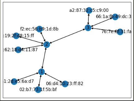
You might not necessarily have the same mac addresses as show here, when you run your network.
When this happens, we would have to get the outport in a slightly different way;
- First, we would have to find the link that connects these two switches together.
- To do this, we iterate through the links we have and check the
dpidof the source and destination of the link. - When we find the link connecting the two switches, we simple get the destination mac address,
- and then perform a simple lookup in the
mac_to_portdictionary to get the out port.
Now to the last step, implementing the _send_packet function.
class MyController(app_manager.RyuApp):
	...

	def _send_packet(self, datapath, in_port, out_port, pkt, dst, src):
		ofproto = datapath.ofproto
		parser = datapath.ofproto_parser
		pkt.serialize()
		data = pkt.data

		actions = [parser.OFPActionOutput(port=out_port)]

		#install a flow to avoid packet_in next time
		if out_port != ofproto.OFPP_FLOOD:
			match = parser.OFPMatch(in_port=in_port, eth_dst=dst, eth_src=src)
			self.add_flow(datapath=datapath,
						  priority=1,
						  match=match,
						  actions=actions)

			out = parser.OFPPacketOut(datapath=datapath,
									  buffer_id=ofproto.OFP_NO_BUFFER,
									  in_port=in_port,
									  actions=actions,
									  data=data)

			datapath.send_msg(out)
			return
		else:
			actions = [parser.OFPActionOutput(port=out_port)]
			out = parser.OFPPacketOut(datapath=datapath,
									  buffer_id=ofproto.OFP_NO_BUFFER,
									  in_port=in_port,
									  actions=actions,
									  data=data)
			datapath.send_msg(out)
			return
Okay so this is the _send_packet function. The way it works is fairly simple;
- First we get our
ofprotoandofproto_parserobjects, - Then we
serializethe packet we want to send and get thedatawe want to send - We then defined the action we want to take, which in this case is to send the data to the
out_port - Now if the
out_portvalue is not set to flood (where we send the data to all the devices on the network),- we would create a new
flow_rule, so that when this kind of packet gets sent on the network, the switch would not have to send it to the controller first. Notice this time thepriorityof theflow_ruleis set to 1, so it has a higher priority that that which was set during theCONFIG_DISPATCHin theswitch_features_handlerfunction. - After this, we create a message to tell the switch to send the packet on to the specified port, with the
parser.OFPPacketOutclass. Theofproto.OFP_NO_BUFFERspecifies that the packet should not be truncated - Finally, we send the message to the switch with the
datapath.send_msg()method.
- we would create a new
- But if the
out_portvalue is set to flood, we flood all the devices.
And that's all for the controller class :)
Now all we have to do is to define out main entry point.
import ...

class MyController(app_manager.RyuApp):
	...

if __name__ == '__main__':
	from ryu import cfg
	cfg.CONF(args=[__file__, '--ofp-tcp-listen-port', '6653'], project='ryu')
	app_manager.main()
In here we specify that the controller should run on port 6653 using the cfg module from ryu, and then we run the app with the app_manager.main() function.
Now let's start our simple SDN.
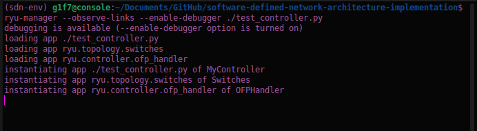
First on your terminal run this command to start the controller:
(sdn-env) gift@console:~/Documents/sdn$ ryu-manager --observe-links --enable-debugger ./custom_controller.py
The output should look something like this:
Next we run the mininet topology script with the command:
(sdn-env) gift@console:~/Documents/sdn$ sudo python3 topology.py
the output should look like this:
Also on the window running the controller, you should see logs saying that the network devices and their links have been detected by the controller:
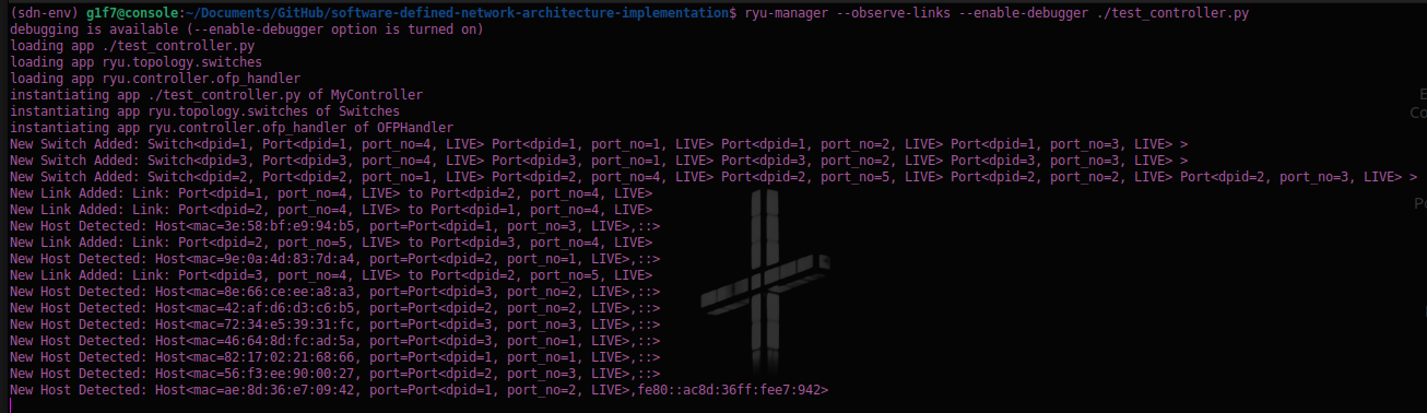
You have to start the controller before running the mininet script so that the controller would be able to detect the host devices
Now for the last step, let's send a pingall command on the mininet console so that we can update the arp table of the switches:
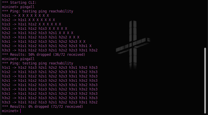
And there you have it, we have now implemented a functional SDN.
But this is just the beginning, there's so much more we could do, like creating a dashboard to monitor the controller and the network using Ryu's REST API, exploring VLANs on mininet, setting up custom configuration for other types of packets, implementing a load balancer, exploring other kinds of routing techniques I mean the list is a really long one.

The good news though is that it all starts from here :)

> I don't really have anything else to say rn
> I'm tired
> I guess this is goodbye for now.
> Sayonara !!!